Cuando queremos crear un robot que distinga el blanco del negro de una superficie tenemos que leer la posición en la que se encuentra con varios sensores infrarrojos.
To make a robot that distinguishes a black area between a white one, we need to know the position of the robot by reading the information of several infrared sensors.
Muchas veces los microcontroladores que usamos para estos robots tienen un número muy ajustado de pines de entrada y salida, y si tenemos que usar uno de estos por cada sensor infrarrojo que utilicemos vamos a tener problemas para añadirle funcionalidades a nuestro robot: Comunicaciones serie, acelerómetros, giroscopios, i2c, sensores de distancia, bumpers, botones, motores, leds, etc.
Many times the microcontrollers used for these robots have a very limited number of in/out pins, so if we have to use one of those for each infrared sensor, we will find problems to add functionalities to our robot as Serial Communications, accelerometers, gyroscopes, i2c, distance sensors, bumpers, buttons, motors, LEDs, etc..
En los robots rastreadores se usan dos sensores infrarrojos como mínimo, en los de sumo se usan 4, en los velocistas suelen ser 6 sensores o más. Todo esto provoca que tengamos que «desaprovechar» pines de nuestro micro para leer los sensores. Sin embargo hay una forma de leer varios sensores de infrarrojos usando sólo un pin analógico del microcontrolador.
Tracker robots at least use two infrared sensors; sumo robot 4 and line follower robot tend to have 6 or more sensors. All this causes the «waste» of the pins of our micro to read sensors. However, there is a way of reading several infrared sensors using only one analog pin microcontroller.
La idea proviene de este artículo, donde se explica cómo se puede leer un teclado matricial de 4 filas x 3 columnas con un sólo pin analógico de un microcontrolador PIC. El objetivo es usar varias resistencias para que, dependiendo de la tecla que se pulse, el pin del micro reciba una tensión distinta y poder discernir cuál es la que se ha pulsado. Aquí tendremos un inversor Schmitt trigger en cuyas salidas pondremos resistencias en serie de distintos valores unidas a un punto en común. Desde ese punto se medirá el valor de la tensión, que será distinto dependiendo del sensor activo, pudiendo conocer así la posición del robot.
The idea comes from this article, which explains how to read a keypad matrix of 4 rows x 3 columns with only one analog pin of the PIC microcontroller. The objective is to use several resistors for, depending on which key is pressed, the micro pin receives a different voltage discerning this way which key has been pressed. At this point, we will have a Schmitt trigger inverter whose output have resistors connected in series of different values attached to a common point. From this point the voltage value is measured, which will be different depending on the active sensor, being able to know the position of the robot.
Primera ventaja: Tener varios sensores CNY70 o un array QTR-8A ya no es un problema porque podemos leer todos los valores con un sólo pin de nuestro microcontrolador y dejar el resto para otras tareas.
First advantage: Having multiple CNY70 sensors or a QTR-8A array is no longer a problem because we can read the values with a single pin of our microcontroller and leave the rest for other tasks.
Segunda ventaja: Por cada sensor que se leía con un pin analógico se provocaba una pausa, ya que la lectura de un ADC tarda un tiempo en hacerse, multiplicado por el número de sensores. Con esta solución sólo se hace una lectura.
Second advantage: Each sensor read with an analog pin causes a pause, since the reading of an ADC takes a while to execute, and this pause must be multiplied by the number of sensors. Using this solution takes only one reading.
Tercera ventaja: Como vamos a usar un inversor schmitt trigger y este sólo nos da una señal alta (5 v.) o baja (0 v.) en sus salidas, con las resistencias siempre vamos a obtener los mismos resultados de tensión aunque cambiemos de entorno (pistas de competición o caseras con distinta iluminación), por tanto no hay que calibrar.
Third advantage: As it is use a Schmitt trigger inverter which only gives a high level (5 V) or low one (0 V) in their outputs, the resistors are always going to get the same voltage if you change the environment (race tracks with different lighting or home), so there is no need to calibrate.
Cuarta ventaja: Con las resistencias correctas sólo es necesario tener un ADC de 8 bits (0-255) para medir el voltaje (en tramos de 0,02 V. aproximadamente) con una referencia de 5 V.
Fourth advantage: With the proper resistors it is only necessary an ADC of 8 bits (0-255) to measure the voltage (0.02 V steps approximately) with a 5 V reference.
Voy a poner como ejemplo 8 sensores infrarrojos que leen una hoja que tiene fondo blanco (devuelven valor cercano a 0) y la línea de color negro (devuelven un voltaje mayor). Como inversor schmitt trigger podemos usar un 40106 o un 74HCT14 que tienen 6 entradas/salidas. Como se necesitan 2 entradas más para alcanzar las 8 hay que poner otro chip inversor (recomiendo distribuirlos en 4 + 4 en vez de 6 + 2). También necesitaremos 8 diodos y 9 resistencias.
Let me give an example of 8 infrared sensors that distinguish a white background (return value close to 0) and the black line on it (that return a higher voltage). As the Schmitt trigger inverter it can be used a 40106 or 74HCT14 which has 6 inputs / outputs. Since it takes 2 more entries to reach the 8 sensor, another chip inverter is necessary (I recommend distribute 4 + 4 instead of 6 + 2). We also need 8 diodes and 9 resistors.
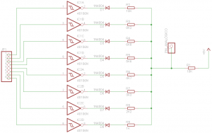
La salida de cada CNY70 o de cada elemento del array QTR-8A va dirigido a una de las entradas de uno de los inversores.
The output of each CNY70 or each element of the QTR-8A array is routed to one input of one of the inverters.
La salida correspondiente de ese inversor va a un diodo enfrentado. Esto es necesario ya que al juntar al final todas las salidas evitamos que si una salida esta a 5 v. y otra a 0 v. se derive la corriente entre ellas.
The corresponding output of each inverter is routed to a faced diode. This is necessary since it prevents the pass of current among outputs in different states (one output in 5V and another at 0V).
Después del diodo viene la resistencia, que dependiendo del valor que tenga hará que la tensión caiga más o menos. El valor de la resistencia debe ser único con respecto al de las otras para que la caida de tensión sea diferente.
After the diode, it is placed the resistor, which depending on its value, the voltage will decrease more or less. Each resistor value must be unique in the set so the final voltage was different.
Finalmente se unen todas las salidas en otra resistencia para crear lo que se denomina un divisor de tensión. En ese punto se debe poner la línea que une al pin analógico del microcontrolador para que este pueda medir el voltaje total y diferenciar qué sensor o sensores están activos. Esta resistencia final que une al resto va a alimentación (Vcc). Esta configuración esta diseñada para poder leer el fondo blanco con una línea negra siempre y cuando los sensores nos den un valor cercano a 0 para cuando leen el fondo blanco y un valor mucho mayor para cuando leen la línea negra. Si se necesita cambiar este comportamiento, se puede conectar la resistencia final a masa e invertir los diodos.
Finally, all outputs are joined together in another resistor to create what is called a voltage divider. In that point you may put the line connected to the microcontroller’s analog pin so the total voltage can be measured and distinguish which sensor or sensors are active. This final resistor that joins the other ones must be connected to Vcc. This configuration is designed to read a black line on the white background as long as the sensors give us a value close to 0 when reading the white background and a much greater value when reading the black line. If you need to change this behavior, you can connect the ending resistor to ground and reverse the diodes.
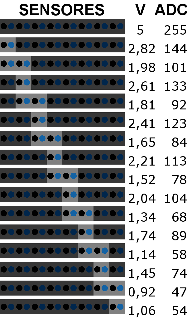
Ahora que ya recibimos distintas tensiones en el pin analógico de nuestro microcontrolador dependiendo de los sensores que estén activos o no, debemos plantearnos cuántas medidas posibles podemos tener. Como he puesto un ejemplo de un velocista podemos tener los siguientes casos:
- Todos los sensores leen el fondo blanco.
- Un sensor lee la línea negra y el resto el fondo blanco.
- Dos sensores leen la línea negra y el resto el fondo blanco.
Now that we got different voltages in the analog pin of our microcontroller depending on the sensors that are active or not, we must consider how many possible measures can we have. As continuing with the example of the line follower, we have the following cases:
- All sensors read white background.
- One sensor reads the black line and the rest, white background.
- Two sensors read the black line and the rest, white background.
Así pues según la combinatoria, debemos multiplicar el número de sensores por 2. En total tenemos 16 medidas posibles (y diferentes) para todos los estados que pueden tener nuestros sensores. Pongo un esquema con los distintos estados, el voltaje resultante según una simulación y su valor de ADC de 8 bits:
Using Combinatory, we must multiply the number of sensors by 2. In total there are 16 possible (and different) measures for all states which can have in our sensors. I put a scheme with the states, the resulting voltage according to a simulation and its value in 8-bit ADC:

Aquí dejo un vídeo de una simulación en proteus sobre la activación de varios sensores (verlo en HD y a pantalla completa):
Here I show a video of a simulation in proteus on the activation of multiple sensors (see this in HD and full screen):
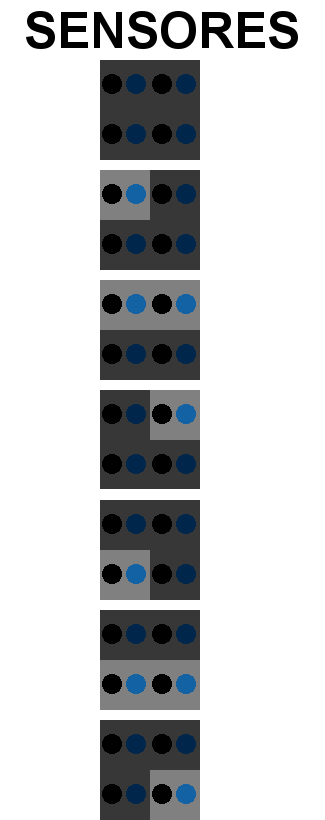
Para uno de sumo ya no valdría el cálculo anterior ya que habría 7 combinaciones posibles con sus 4 sensores y el fondo es negro con una línea blanca:
For a sumo robot the previous situation is no longer valid as it would be 7 combinations with 4 sensors and the background is black with a white line:

Ahora sólo quedaría medir una primera vez los distintos valores de los sensores y luego programar en nuestro microcontrolador una tabla con esos valores que nos servirá para siempre. Por supuesto como los valores de las resistencias tienen un margen de error y la caída de tensión de los diodos no suele ser siempre el mismo, sólo podremos hablar de valores orientativos y únicamente podemos sacar los valores correctos midiéndolos directamente con un polímetro o que el microcontrolador nos lo diga a través del puerto serie. Yo he probado con valores consecutivos de resistencias comerciales y me ha funcionado bien.
Last action to take is to measure the different sensor values and then program a table in our microcontroller with those values that will be correct for us forever. Of course, the values of the resistors have a margin of error and the voltage drop across the diodes is not usually the same: we are talking only about approximate values and we can only get the correct values by measuring directly with a multimeter or with the microcontroller and sending it trough the serial port. I’ve tried commercial consecutive values of resistors and it has worked well.
Finalmente comentar que si nuestro micro no tiene pin analógico pero si tres pines digitales libres podemos usar un ADC0831.
Finally, I would like to remark that if our micro does not have an analog pin but three digital pins, we can use an ADC0831.
Gracias a Maiki por la traducción / Thanks to Maiki for translation


Buen articulo, otra forma de ahorra pines
gracias por compartir
Gracias. La única pega es que los sensores se leen como si fuera en digital en vez de en analógico, pero el Robot Zero también lo hace así y funciona muy bien 🙂
Otra opción es usar un MCP23017
http://ww1.microchip.com/downloads/en/DeviceDoc/21952b.pdf
Al tener que usar I2C (2 pin) o SPI (4 pin) ya estamos perdiendo la ventaja de manejar un sólo pin, además de que esos buses de comunicaciones tienes que mandar y recibir comandos y datos, por lo que obtener el estado de los sensores no es tan directo. Sin embargo el de I2C es una buena opción para cuando no se tiene un pin analógico ya que sería lo suficientemente rápido para no demorar un control PID y se usarían 2 pines solo.
Esto es control PID?
No
Los sensores como estarían conectados? Con resistencia de 220 ohm y otra de 18k?
Las resistencias son las que aparecen en el esquemático. Pulsa sobre la imagen para verlo más grande.
El voltaje de salida al pin del controlador me queda constante no me esta variando…
Pueden ponerse mas de 16 sensores en un pin?
En teoría si, pero la resolución de bits del pin analógico tiene que ser suficiente para detectar pequeñas diferencias de voltajes.