0-Introduction:
Some time ago I read an article about a contest called AFRON design challenge. The target of this contest is to get an affordable robot, with a cost of 10$, for learning robotics in schools.
So I thought it was a good cause to participate. I was thinking in a very simple autonomous robot (Traditional category in the contest), so I had the idea that a good point of departure to learn is a light follower: the robot sensors are seeking if there is a light source and when they find a light the robot goes toward it.
I looked for the components, made the robot and at the end I have finished to L.I.O.S. (light input output system).
All images (except components and tools) in this article can be zoomed by clicking on them.
1-Description:
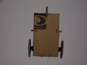
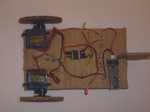
The wheels and chassis are made of cardboard from a recycled box. The sensors are LDR, the motors are two modified servos for continuous rotation, the brain is a pic 12f683 microcontroller, it has two led diodes to indicate the state and a lipo batery to power the system.
When battery is plugged, the leds blink several times. The microcontroller is checking continuously the two LDR, if it detects a high light intensity in one of them, then it turns on the led at the same side that the LDR and activates the opposite side’s servo (if the light source is at right, then the left wheel is which has to move and viceversa); if both sensors detect the light, then the two leds are turned on and both motors are activated to go straight forward; if it doesn’t detects light then the robot remains stopped and the leds are turned off.
As you can see below, the total cost is 10.73$, very close to target price.
The robot is designed to be builded from scratch with common and accesible components and tools.
Consumptions
23 mA if the robot is stopped.
Till 300 mA when is following a light.
Speed
8,7 cm/s when the battery level is 3.7V
2-Educational applications:
Students build an entire robot in a short period of time.
They learn electronics, mechanics and programming.
They study the differential wheeled motor.
They obtain soldering skills.
They obtain microcontroller programming skills (in this case in C language).
They are able to use CAD software to design electronics or structures.
They are able to interpret schemas.
They can test how the light changes the resistor value in a LDR.
Thay can learn the resistor color code.
They can measure the voltage and current with a multimeter.
They can recycle components.
The can modify and improve the robot with their own ideas.
And probably the most important: When they sets out to do something, they achieve it.
3 – Components:
| Name | Description | Unit price (link) | Quantity | Total | |
|---|---|---|---|---|---|
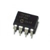 |
PIC12F683 | The brain | 1.78$ | 1 | 1.78$ |
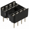 |
DIP socket | To insert or remove the PIC | 0.18$ | 1 | 0.18$ |
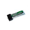 |
Lipo battery | To power the system. 3.7V (1 cell) and 130mAH. | 1.33$ | 1 | 1.33$ |
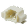 |
Male connector | To plug the battery | 0.47$ | 1 | 0.47$ |
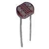 |
LDR | To detect the light | 0.32$ | 2 | 0.64$ |
 |
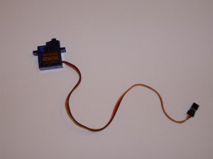
Servo | To move the robot | 2.69$ | 2 | 5.38$ |
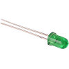 |
Led diode | To show the state | 0.13$ | 2 | 0.26$ |
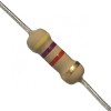 |
180Ω resistor | For the leds | 0.08$ | 2 | 0.16$ |
 |
10KΩ Resistor | For the LDR and servos | 0.08$ | 6 | 0.48$ |
| Others | Cardboard (any recycled box), wires (use the cut ones from the servo), solder, glue and heatshrink sleeve | 0.05$ (recycled materials or minimal quantities) | 0.05$ | ||
Total |
10.73$ |
||||
The battery is the only component you will have to replace. The life cycle of lipo battery is about 400 charges before get rid of it in household waste recycling centre.
4-Tools
| Name | Target | Estimated price | |
|---|---|---|---|
 |
Fixed blade trimming knife | To cut the cardboard | 4$ |
 |
Glue | To stick the cardboard, servo arms and servos | 3$ |
 |
Adhesive tape | To stick the template and battery to the cardboard | 1.50$ |
 |
Needle | To pierce the cardboard | 0.02$ |
 |
Hot glue gun | To stick the LDR, leds, resistors and socket to the cardboard | 15$ |
 |
Pistol automatic wirestripper | To strip the wires | 10$ |
 |
Lighter | To shrink the heatshrink sleeves | 2$ |
 |
Flush cutter | To cut the servo’s gear stop, wires, leads and heatshrink sleeves | 5$ |
 |
PH0 screwdriver | To drive the servo screws | 1$ |
 |
Soldering iron | To solder the wires with LDR, leds, resistors, connector and socket | 10$ – 25$ |
 |
Solder | To solder | 5$ |
 |
Programmer | To program the PIC | 14$ – 45$ |
 |
Battery charger | To charge the lipo battery | 15$ – 75$ |
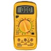 |
Multimeter | To measure the lipo battery charge | 5$ – 30$ |
5-Drawings
Structure
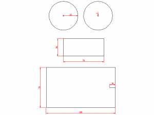
Print the first layer of this DXF template to scale 1:1. I have used an open source application called LibreCad. Click to zoom:
Electronics
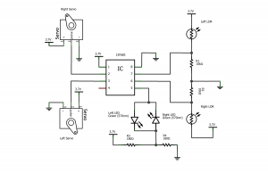
This is the electronic schema. I have used an open source application called Fritzing. Click to zoom:
6-Build Instructions:
Servos
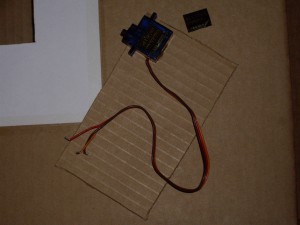
The servos include electronics to manage their rotation direction and have gears to increase their traction strength, however they only can rotate 180 degrees, so we have to modify them to become in a continous rotation motor.
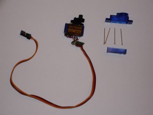
First of all is to strip extracting the 4 base screws and detach the top and bottom covers:
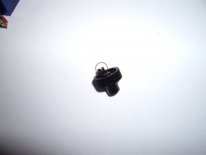
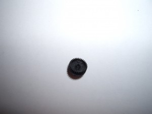
Then you have to extract the gears. One of them has a tab for making contact and don’t advance anymore (marked as a red circle):
This is the result after cutting the tab:
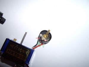
The servo has a POT. We have to desolder the wires (green arrows) and break the wall which contains the two making contact tabs (red arrows):
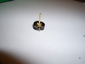
This is the result after breaking the wall:
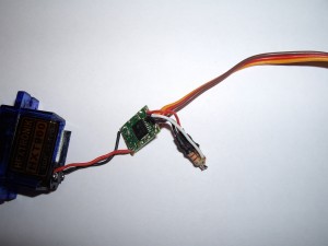
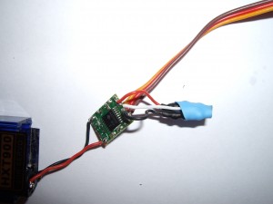
The next step is to solder the two 10KΩ resistors making a voltage divider with the previous step’s desoldered wires (the white wire goes between the two resistors). To isolate the contacts use heatshrink sleeve:
Isolate the other end with heatshrink sleeve:
Finally join all gears again, insert the electronics, put the covers and screw on:
Chassis and wheels
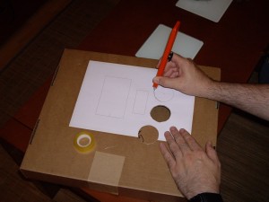
Stick the template paper to the cardboard with adhesive tape. Pierce the little circles with a needle and cut the lines with the trimming knife.
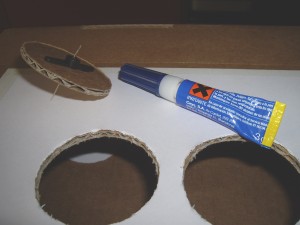
After that, insert the needle trough the wheel hole, Put some glue in the straight servo arm and introduce its central hole by the needle until making contact with the wheel. Repeat the process with the other wheel:
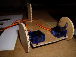
Remove the sticker from left servo’s side, put some glue in that lateral and stick it on the big cardboard surface at the top left end. Repeat the process at the other side with the other servo:
Cut slightly the small cardboard surface by the one third, put some glue there and stick it to the incision made before in the big cardboard surface (according to the template). Place the two wheels to the axis of the servos:
Pierce 4 holes between the servos, insert the LDR from the bottom side, rotate them 30 degrees from the center and stick them with hot glue. Pierce two holes at both sides, insert the led diodes from the bottom side and stick them with hot glue:
Electronics
LDR
- Solder one of the leads of each LDR to VCC.
- Solder the other lead of each LDR to one end of a 10KΩ resistor.
- From the previous left union, solder a wire to socket pin 7 and put heatshrink sleeve.
- From the previous right union, solder a wire to socket pin 6 and put heatshrink sleeve.
- Solder the other end of each resistor to GND.
- Stick the resistors to base with hot glue.
Servo
- Strip the wires and solder the red one to VCC and the brown one to GND in each servo.
- Solder the orange wire of the left servo to socket pin 3 and put heatshrink sleeve.
- Solder the orange wire of the right servo to socket pin 2 and put heatshrink sleeve.
LED
- Solder one of the leads of a 180Ω resistor to VCC.
- Solder together the loose lead from previous resistor with one of the leads from the second resistor.
- From previous union, solder a wire to the right led’s anode.
- From previous union, solder a wire to the left led’s cathode.
- Solder the second resistor’s remaining end to GND.
- Stick the resistors to base with hot glue.
- From the right led’s cathode, solder a wire to the left led’s anode.
- From previous union, solder a wire to socket pin 5 and put heatshrink sleeve.
PIC
- Solder the socket pin 1 to VCC and put heatshrink sleeve.
- Solder the socket pin 8 to GND and put heatshrink sleeve.
- Stick the socket to base with hot glue.
Battery connector
- Plug the connector to battery and check which lead is positive (or 3.7V) and which lead is negative (or 0V.) with a multimeter.
- Extract the battery from connector and solder a red wire from positive lead to VCC and a brown/black wire from negative lead to GND. Put heatshrink sleeve.
Precautions
- The trimming knife’s blade is sharp, take care of cutting yourself with it.
- The needle is sharp, take care of pricking yourself with it.
- The glue is strong, take care of touching it with your skin or contacting your eyes.
- The hot glue is really hot, take care of touching it with your skin.
- The iron solder is hot, take care of touching it with your skin nor contacting the cardboard and avoid to breath the solder smoke.
- The lipo battery must not be short circuited, nor overcharge above of 4.2V. nor discharge below of 3V.
- The lighter flame is very hot, take care of touching it with your skin nor contacting the cardboard
7-Mass Manufactured:
This robot can’t be sent to build in mass.
8-Software:
From here you can download the source code of the PIC firmware (GPL licensed). If you want to understand the running of the registers of PIC 12F683 , the best is to read the datasheet.
From here you can download the .hex file to program the PIC.
The compiler I have used is SDCC, which is free software. I have typed the following command to compile it:
|
1 |
sdcc -mpic14 -p12f683 --use-non-free lios.c |
When you want to upload the .hex file to the pic you have to own a PIC programmer and a software that manages the programmer. There is a lot of variety. I have used the pickit3 from Microchip and its software for windows, but there are other alternatives more cheaper that can be used with free software or freeware for linux, mac and windows.
Explanation
In general terms the running is:
When battery is plugged, the leds blink 10 times quickly. The leds have a special configuration, so if the PIC pin is configured as output and put it high, then the left led is lighting, if the PIC put the pin low, then the right led is lighting; if the PIC pin is configured as input (high impedance) the leds remain off.
The timer0 and ADC interrupts are activated. The timer0 interruption is configured for triggering each 0.1 ms.; its functionality is to count the servos timings. The ADC interrupt is triggered each time the ADC conversion is finished; its functionality is to activate the associated led (if a threshold exceeds), put a value in a state variable, change the ADC channel and read the next LDR.
Inside the main loop of the program, it is checking the state value for knowing what servos have to be activated. The activation of the servos is different due to they are put face to face and the rotation to go straight forward is distinct in each one. One of them has to have signals of 1 ms. high and 19 ms. low, while the other has to have signals of 2 ms. high and 18 ms. low.
9-Experiments conducted
See the 11th section.
10-Pictures
You can see some pictures along the article.
11-Video
12-Modifications:
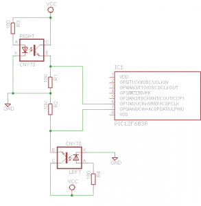
The robot sensors are LDR, but they could be changed by two CNY70, obtaining a line follower robot with the next schema:
You have to change in source code the line
|
1 |
if(value > BOUNDARY) |
by this one
|
1 |
if(value < BOUNDARY) |
And perhaps change the threshold value (BOUNDARY define).
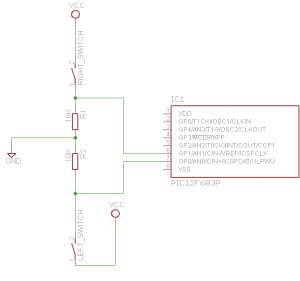
Also the sensors can be changed by two snap action switch, obtaining a clashes detection robot with the next schema:
In this case you don’t need to change any source code.

Pingback: L.I.O.S.: The ten-ish dollar robot. - Hack a Day
Pingback: Belgaum news | About Belgaum | Belgaum information | Belgaum district | Belgaum city | Belgaum Hotels | Belgaum People | Belgaum tourism | Belgaum entertainment | Belgaum students | Inside facebook | Hack | make use of | technical news | | L.I.O.S.: The t
Pingback: Indagadores |Seguridad informatica |Seguridad en internet » L.I.O.S.: El robot de diez dólares-ish.
Hi,
Im a member of a french Hackerspace (www.electrolab.fr). I’d like to translate into french your documentation and use it in various workshops.
I also plan to use an attiny85 instead of the pic.
Would that be okay ?
Cheers !
Hi
Of course you can. Good luck!
Amigo, yo no podía comprar el 12F683 PIC. Me acababa de comprar el PIC 12F675. Pero creo que tienen algunas diferencias significativas. ¿Qué cambios tengo que hacer que el código fuente para que el proyecto funcione correctamente?
Lo siento, pero soy bastante lego en la materia.
————————————-
Dude, I could not buy the PIC 12F683. I ended up buying the PIC 12F675. But I think they have some significant differences. What changes would I have to make the source code to make the project work properly?
I’m sorry, but I’m fairly layman on the subject.
Supongo que si, parecen bastante similares http://www.microchip.com/wwwproducts/ProductCompare.aspx?product1=PIC12F675&product2=PIC12F683 y ambos son soportados por sdcc, sin embargo el oscilador interno del 675 es de 4 MHZ y el de 683 es 8 MHZ por lo que tendrás que cambiar los tiempos del timer.
Olá, estou tentando montar es infse projeto, porém o PIC informado nao está sendo fabricado mais, posso utilizar o PIC 16F628A ? Qual modificação que terei que fazer?
why does the motor rotate so slowly?
Because it is powered to 3.7V.
I used protheus to simulate the lios.hex source code..i used an ordinary DC Motor..thanks for ur fast response!